Balsa Wood Bridge
Sam Katsuda

Pratt Bridge with Lifting Mechanism Drawing
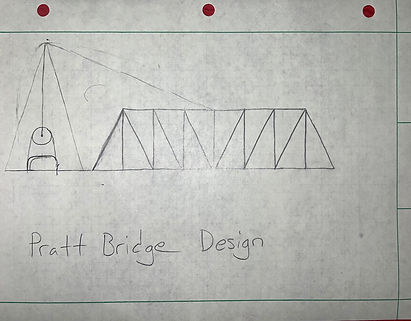
Pratt Bridge with Lifting Mechanism Sketch
Introduction
The objective of this project was to create and articulating balsa wood bridge that would span across a gap and support a load. The student was tasked to use their engineering knowledge to design, manufacture, and test a bridge. It must span a gap of 400mm, hold a static load of 20 kg at the center, and articulate up to 140mm at the center. The method for articulation can be done in any means, but needs to be able to hold the bridge at max height for 10 seconds, as well as have the weight of the articulation structure and the weight of the bridge under 85g.
To tackle this project, the bridge design used was a Pratt style. Calculations for cross sectional area of the beams was done to determine both the minimum area as well as the area with a safety factor. Articulation was accomplished using a pully system and Arduino controlled motor. Components necessary for articulation were manufactured using a 3-d printer. The structure for the pully system will form a pyramid that will have a cable running over the top to the top center of the bridge.
Requirements
1. The bridge and articulating structure must only be made from balsa wood and wood glue (not including articulation components).
2. The bridge needed to span across a 400mm gap.
3. The bridge must allow a 100 mm object (perpendicular and above the abutment plane) to traverse the width of the bridge.
4. The bridge needed to be slightly longer than 400mm to rest on 60mm wide steel abutments.
***5. The total weight of the bridge and Articulating structure may not exceed 85g (not including articulation components).
6. This road deck must be within 12 mm of the top surface of the abutment. The end of the road deck must be withing 12 mm of the vertical surface of the abutment.
7. The bridge must have a solid balsa wood deck with only an 8mm diameter hole in the center for testing.
8. The bridge deck must be 38mm wide, to allow a 32mm wide by 25mm high block to pass through the bridge free of obstruction and at a constant velocity.
***9. The bridge must not deflect more than 25mm.
***10. The bridge must be able to articulate 140mm vertical at the center and hold in place for 10 seconds.
***11. Ascend and descend must be done by the push of a button and take less than 60 seconds. ]
***12. The bridge must be able to support 20kg about the center
*** = Primary Focus
Results
This section will outline the results of the project as well as what could have been improved and what fixes would be done in future iterations.
Results
Test 1
Articulation Height Test
What was found in this test was that the bridge was able to articulate to a height of 142.6 mm which was 1.86% over the predicted value of 140mm. As it was over the requirement the bridge does pass this test.
For future iterations, sensors would be used to allow the bridge to stop at the same spot every time. This would also allow the bridge to be run off one button rather than three which would allow the bridge to have a more precise lift.
Test 2
Articulation Cycle Time
Following the cycle time test it was found that the bridge cycle time was 15.216 seconds which is below the predicted 17.4 seconds and below the 60-second requirement so the bridge does pass this test as well. It was also able to maintain a max articulation for 10 seconds so it does pass that test as well.
One issue that ran into with this test was that the bridge would lift and lower at inconsistent rates, with sometimes it lowering by slamming down as if done by gravity. To solve this a mechanism could be installed to lower the gear ratio of the bridge to give it an easier time lifting and lowering the bridge. Another solution would be to buy a motor with better low end torque leading to the same result as the lower gear ratio but built into the motor.
Test 3
Load and Deflection Test
The results of this test were that the bridge was able to maintain a load of 9.7kg while deflecting around 4.03mm, so it was below the required and predicted 20kg. This means the bridge did not pass this test. It did meet the deflection requirements as it was below the predicted 6.9mm and 25mm max requirements. The results are inconclusive though as it was unable to reach the 20kg requirement so the deflection at that point is undetermined.
For future iterations, there are a couple of fixes that could be done. One is that the bridge was built with the grains stacked top to bottom meaning the grains would be split under tension. If they were stacked side to side, then they would be able to maintain a higher load under tension without fail(the break can be seen in Figures 1 and 2 below). Another fix would be to increase the cross-sectional area of the beams as the bridge was far under-weight meaning more material could be used to strengthen the structure.
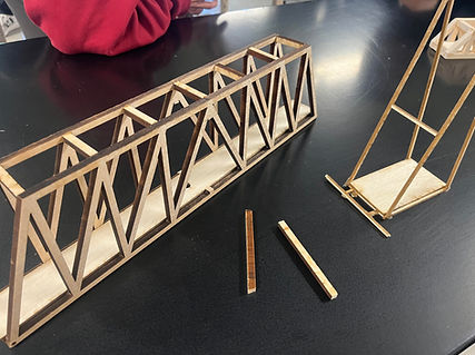
Figure 1: breaking point
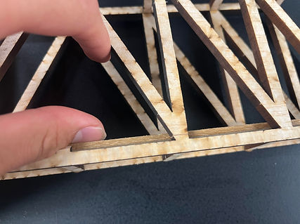
Figure 2: fractures
Result Breakdown
Table 1: Results
